Monigear SNMP User Guide
If the configuration of your device is inconsistent with the documentation, you can contact our technical support and the product can be upgraded to the latest version to apply new features.
Brief introduction to protocols
Simple Network Management Protocol (SNMP) is a protocol used to manage network devices. SNMP is the communication protocol between the Network management software(NMS) and the SNMP agent.
As an SNMP agent, the Monigear devices supports the V1/V2c/V3 versions of the SNMP protocol and provide a standard management information base (MIB), allowing NMS to use the SNMP query and collect data of the device through SNMP GET, modify the parameter value of the device or realize remote control of supervisory points through SNMP SET. (Currently, SNMP TRAP is not available yet)
Enable SNMP on the Monigear device
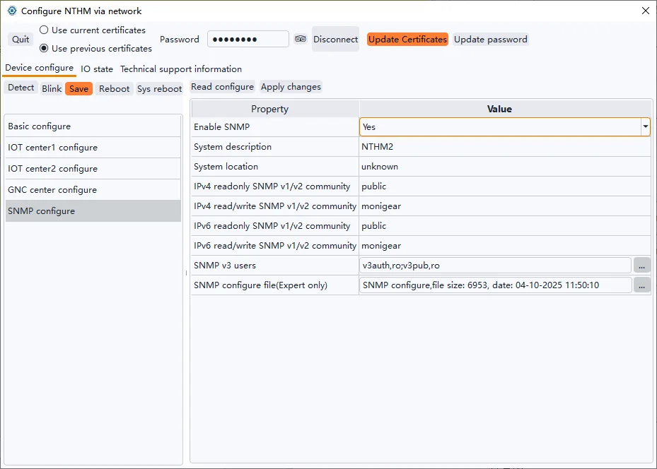
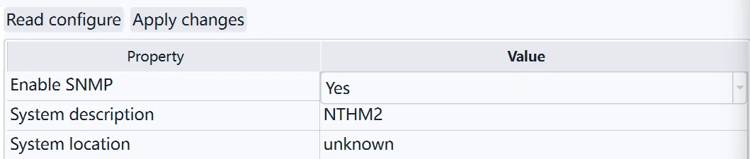
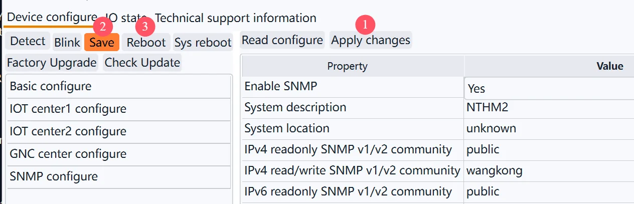
Using the Monigear network device configuration tool, after connecting the device, enable the device SNMP feature in the SNMP configure category.
After modify the configure, you need “Save” and “Reboot” to take effect.
SNMP v1/v2c test example
The following takes the network temperature and humidity transmitter(MN-NTHM) as an example, enable the SNMP function, and use the test tool MIB Browser to read the real-time temperature and humidity data. Note: The personal version of iReasoning Mib Browser can be used for free, but it can only be used to access the SNMP v1/v2 functions. The paid version can use the SNMP v3 functions.
Set device IP and enabling SNMP feature
Please refer to the documentation of the configuration tool for how to set the device IP, and see Figure 1 above for how to enable the SNMP function.
Get the device data through SNMP
Check the device current values in configure tool software shown as below.
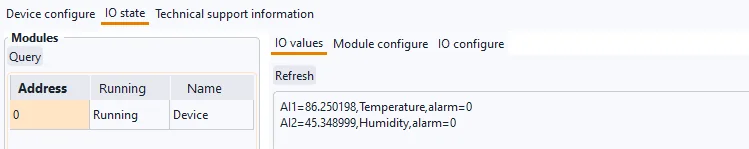
Figure 2
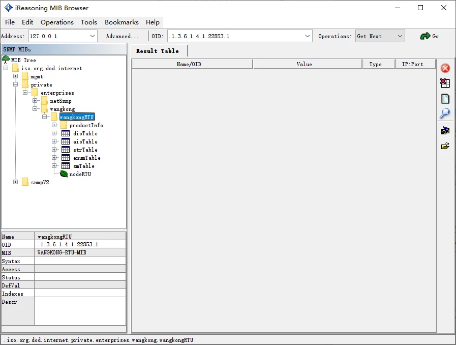
Figure 3
Taking the iReasing MIB browser software under Windows as an example, the steps to retrieve the current temperature and humidity values through SNMP are as follows:
Install and open the MIB Browser, select File->Load MIBs from the menu bar, select and open the MIB file (WANGKONG-RTU-MIB.mib) in the pop-up dialogue box, expand the MIB tree on the left, and find the wangkongRTU level. Show in figure 3.
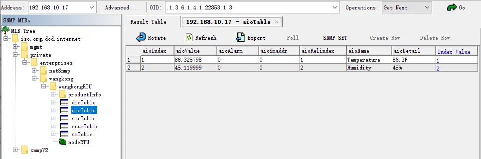
Enter the device IP in the Address field, click Advanced, and set the SNMP parameters in the pop-up dialog box, with the default port number 161; Enter public in the Read Community input box ; Select SNMP Version 2.
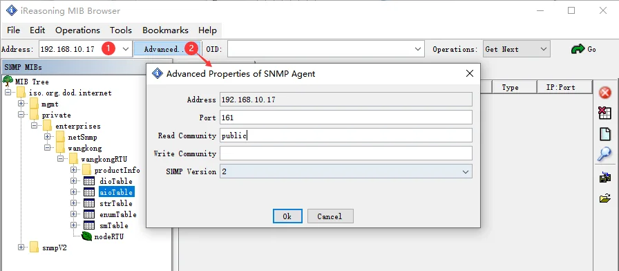
Figure 4
In the MIB tree on the left, right-click aioTable and select Table View to view the supervisory point data in a tabular format.
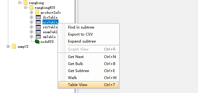
Figure 5
View the temperature and humidity of the device using SNMP
SNMP v3 user description and examples
SNMPv3 offers significant security improvements over SNMP v1/v2c, making it the preferred network management protocol for internet devices and devices with high security requirements. SNMP v3 is highly complex, and administrators need to configure multiple variables, including username, password, authentication, and encryption configuration, to ensure the normal operation of the system. Mis-configurations can cause SNMP to function abnormally, so need to be treated with caution.
This is a simple example of adding a SNMP v3 user and using that user to read the temperature and humidity data of the device.
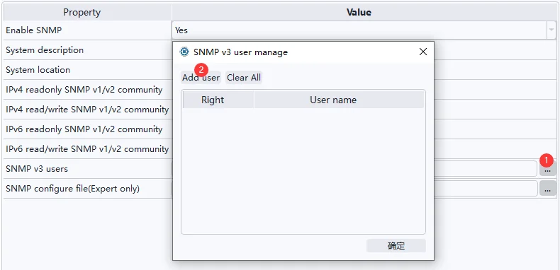
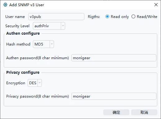
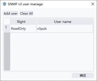
For example, add a read-only user v3pub, select Security Level Authentication and Encryption (authPriv), select MD5 for hashing algorithm, enter the authentication password, select DES for encryption method, enter encryption password, and click OK.
You can add up to 5 users. Note: Added users cannot view or modify the encryption authentication method and password, and cannot delete or modify a single user, you need to clear all users with one click and add new one again.
There are several ways to use the above V3 user to perform communication test and read temperature data:
On a Linux system or msys2 in windows, use the snmpget tool in the net-snmp software pakage, to test and obtain the temperature value.
snmpget -v 3 -l authPriv -u v3pub -a MD5 -A monigear -x DES -X monigear 192.168.10.17 .1.3.6.1.4.1.22853.1.3.1.2.1

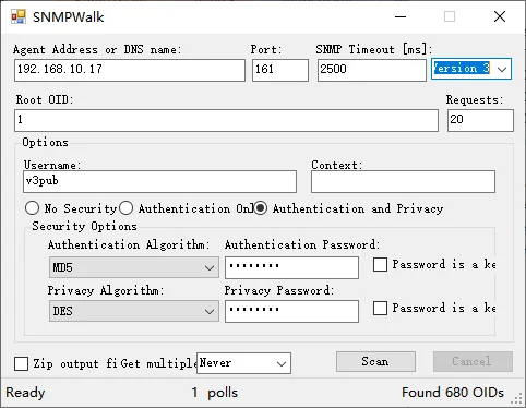
Some software vendors provice Windows tools that can browse and query snmp v3 data, such as SolarWinds' SNMPWalk tool. Select Version 3, fill in the corresponding v3 user information, then click Scan, select a storage path for the scan results, and then start scanning.
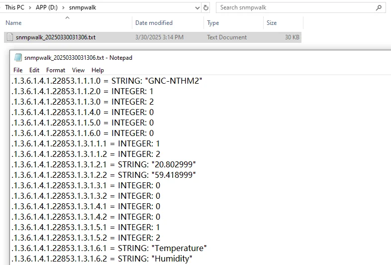
Open the scan results and find the OID and monitoring values of the temperature and humidity data.
To remotely control the relay channels 1~4 of MN-NIO (General IO Monitor) to close or open, it is recommended to use SNMP SET based on SNMP v3, and it is necessary to add a v3 read/write user on the NIO device in advance.
To control relay channel 1 Close:
snmpset -v 3 -l authPriv -u v3auth -a MD5 -A monigear -x DES -X monigear 192.168.10.7 .1.3.6.1.4.1.22853.1.2.1.2.9 i 1
To control relay channel 1 Open:
snmpset -v 3 -l authPriv -u v3auth -a MD5 -A monigear -x DES -X monigear 192.168.10.7 .1.3.6.1.4.1.22853.1.2.1.2.9 i 0

Instructions for using SNMP configuration files
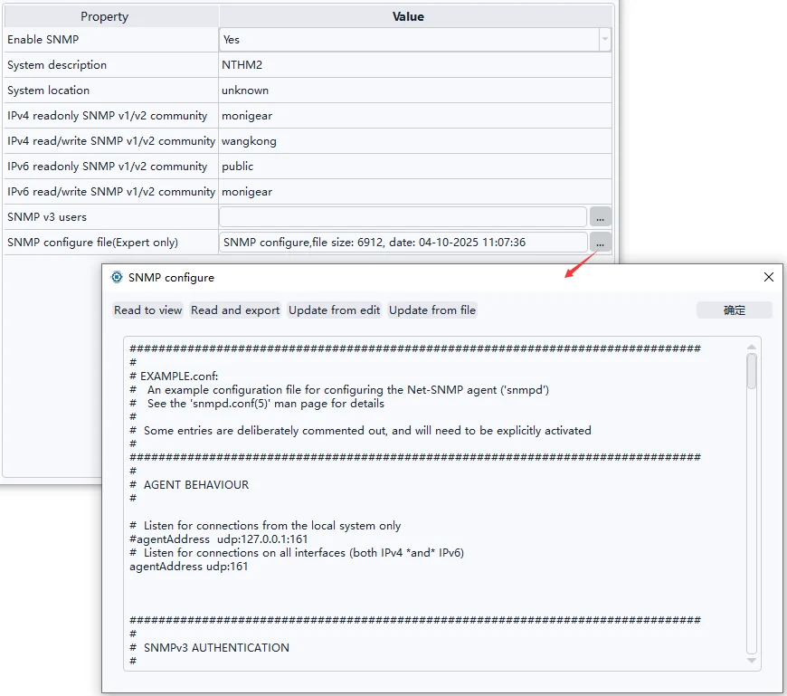
Advanced users can modify the SNMP configuration file to customize the SNMP function of the device. Users can query the configuration details of net-snmp through the Internet, and the following are common configuration modification examples and instructions. The configuration modification needs to be restarted to take effect after the configuration modification is completed.
If the configuration error occurs, the SNMP function of the device may not work properly, so it is recommended to save a copy of the configuration file locally before modifying it. If the configuration file has been wrong and the SNMP service cannot be started, you can manually restore the original file to let the SNMP started as factory default. (see the device manual for details).
Enable/disable IPv4 and IPv6
For example, if IPv4 mode is disabled, only IPv6 mode is retained, and the port number is changed to 1161(The line begin with a hash sign(#) indicates a comment, and this line does not take effect, and the same applies to other configuration lines).
| #agentAddress udp:161agentAddress udp6:1161 |
|---|
In this case, SNMP can only be accessed through IPv6 addresses; for example, Linux uses snmpget to obtain device data through IPv6.

If you need to disable SNMP v1/v2
Comment out all the lines starting with rocommunity, rwcommunity, rocommunity6, and rwcommunity6 (add a # sign at the beginning of the line). This will make the device inaccessible via SNMP v1/v2.
Customize the community name and access policy
Configure the OID root node corresponding to the custom community name and specify the IP address that can be accessed through the custom community name, for example, add the following three lines to the end of the configuration file:
| view monigear included .1.3.6.1.4.1.22853rocommunity rosecret 192.168.1.100/32 default -V monigearrwcommunity rwsecret 192.168.1.101/32 default -V monigear |
|---|
Interpretation:
The first line defines a view named monigear with an OID root node of .1.3.6.1.4.1.22853 (a dedicated OID root node for the monigear brand).
In the second line, a read-only community name rosecret is added, through which only hosts with IP address 192.168.1.100 can access OIDs starting with .1.3.6.1.4.1.22853 (but cannot access public OIDs, e.g., sysDescr.0, .1.3.6.1.2.1.1.1.0).
The third line can read and write the name of the group, and the other lines are the same.
Other
It is worth mentioning that 192.168.1.100 and 192.168.1.101 can still use public to obtain device data.
Here's a closer look at the configuration policy of the configuration tool:
The IPv4 read-only/read-write community names of the configuration tool correspond to the rocommunity and rwcommunity that appear for the first time in the SNMP configuration file, and the IPv6 read-only/read-write community names correspond to rocommunity6 and rwcommunity6 that appear for the first time in the SNMP configuration file, respectively. In this case, the IPv4 read-only community name that the configuration tool views and modifies is the rocommunity added by the user.
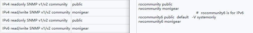
Figure 16
The list of SNMP v3 users is also displayed at the end of the configuration file, but do not modify or delete v3 users indirectly by modifying the configuration file. To add and remove v3 users, you must use the configuration tool throughout the process, otherwise unexpected errors may occur.
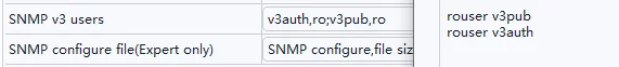
Figure 17
SNMP Trap
The SNMP Trap function of Monigear device supports SNMP v2c and v3 versions(This function is added later. If the device configuration does not see the Trap related content below, you can use the Trap function through device upgrade). When the monitored data point changes reach the threshold, it actively sends a message to the network management system (NMS) to immediately notify the key data point change event without waiting for the NMS to poll the device to obtain information. SNMP Trap is suitable for high real-time scenarios. For large-scale network environment applications, it reduces the polling burden, reduces the network load, and improves the overall response speed of the system.
Note: Currently, you can only set up sending SNMP Trap data to a single network management system. Sending Trap data to multiple hosts is not supported yet.
SNMP Trap test example
Prepare the test environment
The following uses the monigear network temperature and humidity module (MN-NHTM) as an example, uses a Linux host as a server (IP address 192.168.1.105) to receive the SNMP Trap data of the temperature and humidity module, and demonstrates the configuration process and receiving results of the v2c and v3 versions respectively. The Linux system needs to have snmpd and snmptrapd installed in advance.
Reference installation command:
sudo apt install -y snmpd snmptrapd
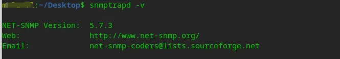
Here, run snmptrapd in the shell terminal to print the received SNMP Trap data packets to the standard console in real time:
sudo snmptrapd -f -Lo -F "%04y-%02m-%02l %02h:%02j:%02k %P [%b][%W]:\n\t%V\n\t % %v\n"

In addition, you can also use tcpdump or other packet capture tools to capture the original UDP network data packets of SNMP Trap to eliminate communication problems caused by IP network links or firewalls:
Reference installation command:
sudo apt install -y tcpdump
Run tcpdump in the shell terminal to capture the data of UDP port 162:
sudo tcpdump -vv -i any udp port 162

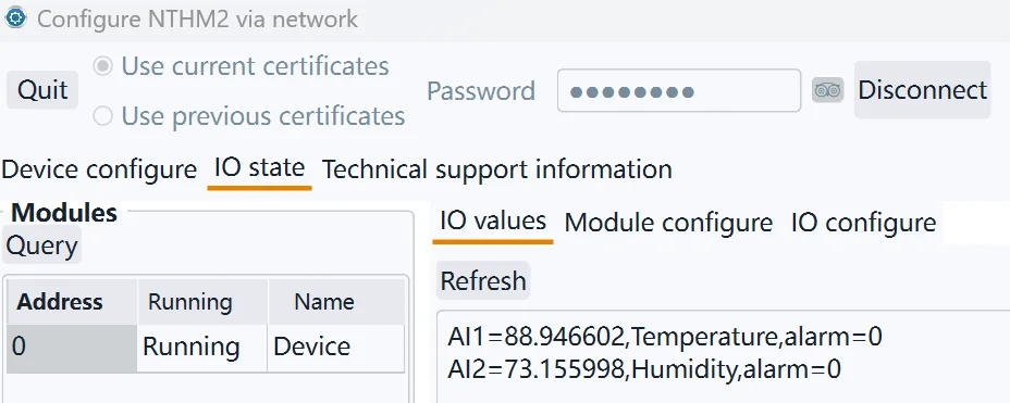
In the configuration tool, click “IO State” -> “IO Values”, click “Refresh” to view the current temperature and humidity measurement values:
SNMP Trap v2c example
① Modify snmptrapd configure file snmptrapd.conf
Edit /etc/snmp/snmptrapd.conf and add a line with the following content, where “monigear” is the community name of SNMP Trap. Then rerun the snmptrapd process in the shell terminal to enable the newly added trap community.
authCommunity log,execute,net monigear
② SNMP v2 trap configure in device side
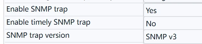
Refer to the figure below for the SNMP Trap configuration of monigear devices. Enable SNMP Trap, select v2c version, enter the server url, and the community name “monigear” (corresponding to the configuration added in the snmptrapd.conf file above).
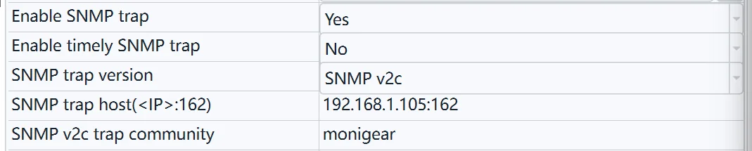
Note that the prerequisite for using SNMP Trap is to enable the SNMP function.
After the settings are completed, click “Apply Changes” -> Save -> Reboot to take effect.
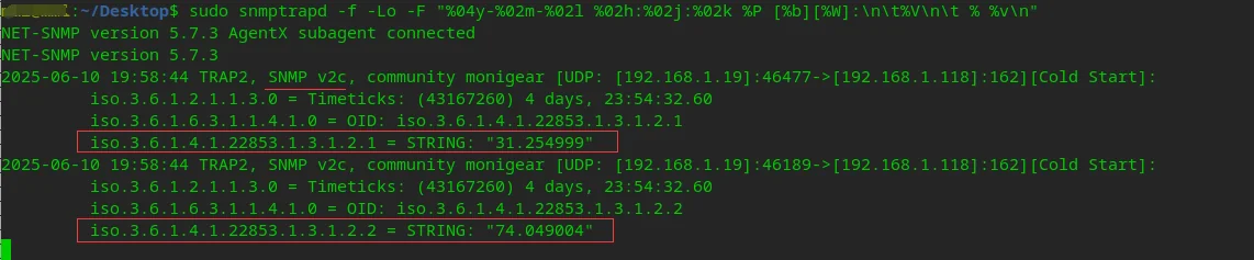
③ Receive SNMP v2 trap data packet
If nothing goes wrong, snmptrapd will receive the SNMP v2c trap data packet sent by the device, including the original temperature and humidity data, as shown in the following figure:
SNMP Trap v3 example
SNMP Trap v3 requires the oldEngineID associated with the local SNMP software package. Use the following command to view it:
sudo grep oldEngineID /var/lib/snmp/snmpd.conf

There are three SNMP V3 security levels: noAuthNoPriv (no authentication and no encryption), authNoPriv (authentication but no encryption), and authPriv (authentication and encryption).
3.1 authPriv mode configuration
① Modify snmptrapd.conf
Edit /etc/snmp/snmpd.conf, add one line like below.
createUser -e 0x80001f8880eca9c86372dd416800000000 v3trapuser SHA monigear AES monigear
Create a user named v3trapuser, use authPriv mode, authentication method SHA, authentication password monigear, encryption method AES, encryption password monigear, and specify the aforementioned oldEngineID. Then re-run the snmptrapd process in the shell command line terminal to load the newly added trap user.
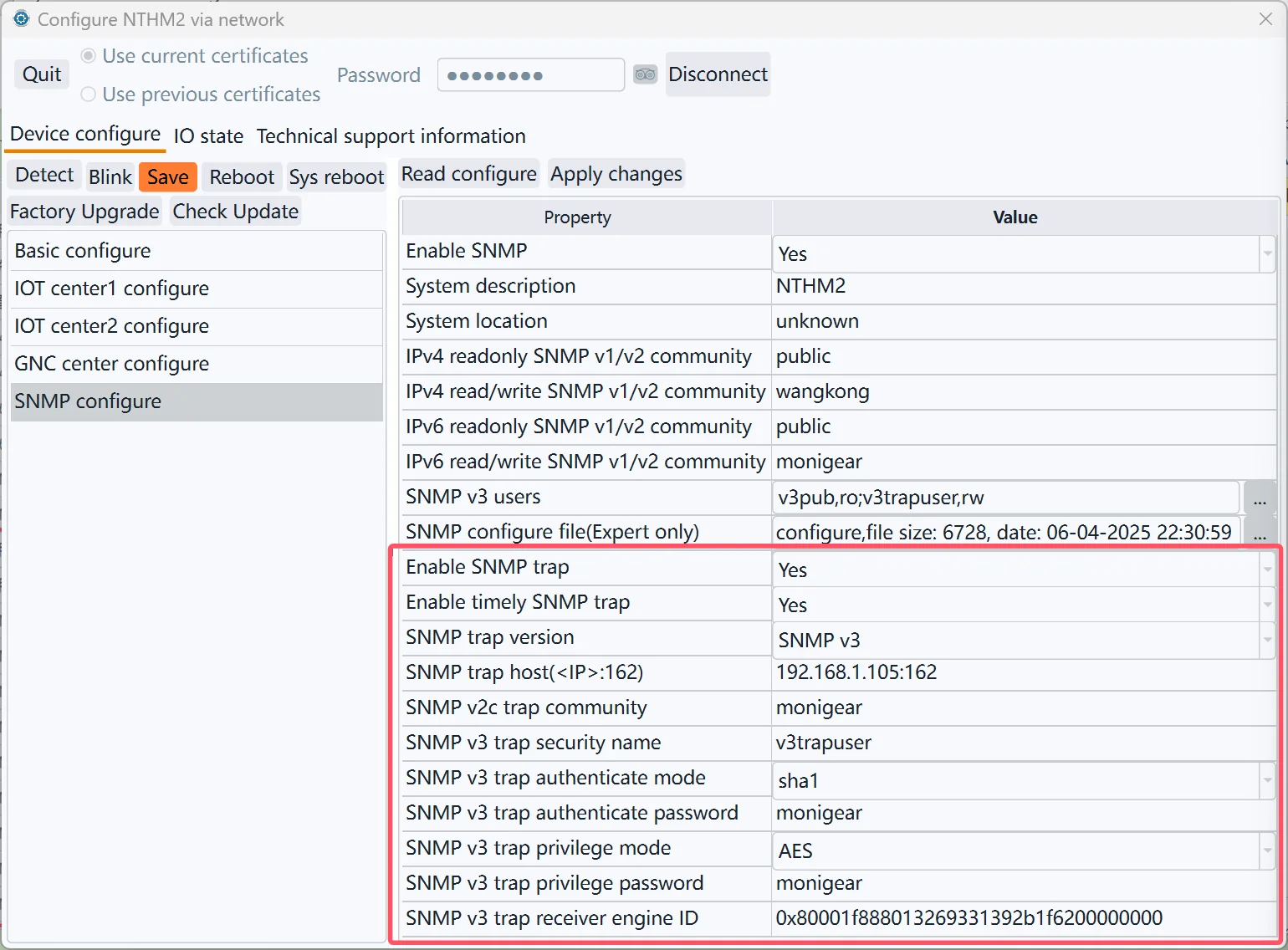
② SNMP v3 trap configure in device side
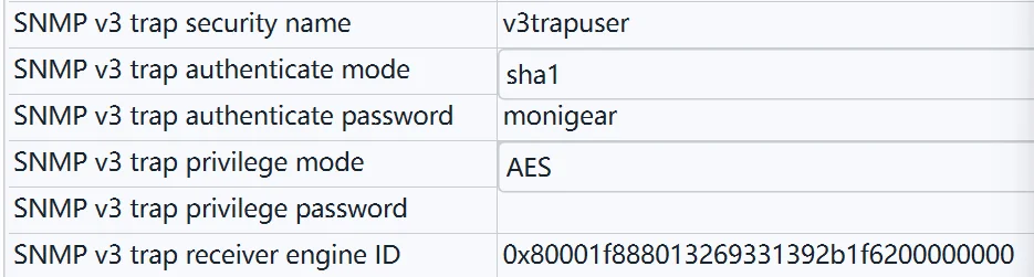
Refer to the figure below for the SNMP Trap configuration of monigear devices. Enable SNMP Trap, select v3 version, and enter the server URL. Each configuration parameter of SNMP v3 trap corresponds to the v3 user added in the snmptrapd.conf mentioned above.
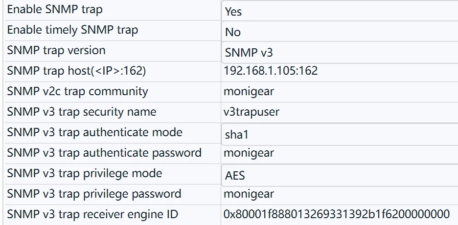
After the settings are completed, click “Apply Changes” -> Save -> Reboot to take effect.
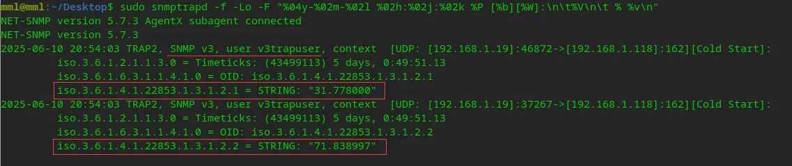
③ Receive SNMP v3 trap packet
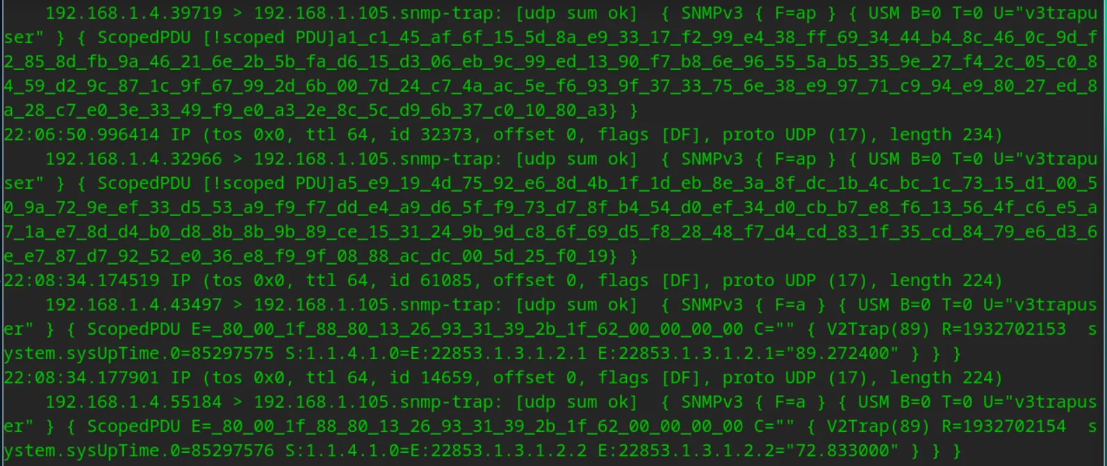
If nothing goes wrong, snmptrapd will receive the SNMP v3 trap data packet sent by the device, including the original temperature and humidity data, as shown in the following figure:
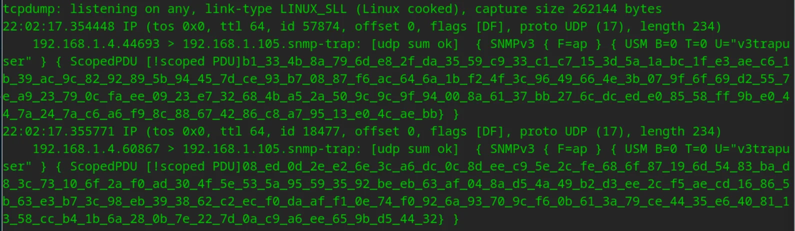
If you use tcpdump, you can see data similar to the screenshot below. tcpdump cannot parse encrypted data.
3.2 authNoPriv mode configure
① Modify /etc/snmp/snmptrapd.conf add a line like below:
createUser -e 0x80001f8880eca9c86372dd416800000000 v3trapuser SHA monigear
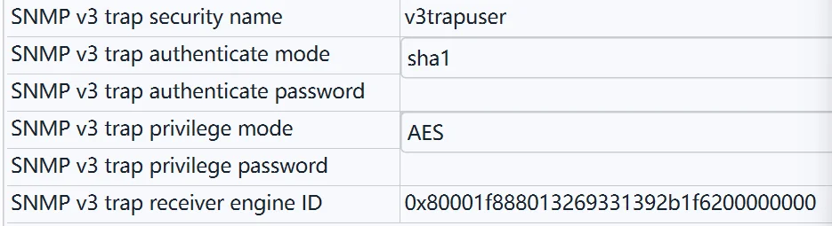
② Device side configuration (configuration items not shown in the screenshot are the same as 3.1)
Compared with the data monitored by tcpdump in authPriv mode, the data received in non-encrypted mode can be parsed to obtain the specific oid value.
3.3 noAuthNoPriv mode configure
① Add a line like below in /etc/snmp/snmpd.conf
createUser -e 0x80001f8880eca9c86372dd416800000000 v3trapuser
② Device side configuration (configuration items not shown in the screenshot are the same as 3.1)
SNMP Trap data type
SNMP Trap only sends the original value of the monitoring point, without the displaying value, alarm level and other information. Refer to the appendix. For details on the OID of the original value, refer to the device MIB description.
| SP Type | DIO | AIO | ENUM | STRING |
|---|---|---|---|---|
| Data type | Bool(0/1) | Float | Int | String |
| Trap OID | dioValue | aioValue | enumValue | strValue |
| Trap Syntax | INTEGER | OCTET STRING | INTEGER | OCTET STRING |
SNMP Trap condition
Monigear devices support a variety of standard communication protocol interfaces, including MQTT, SNMP, Modbus TCP and BACnet, which are convenient for integration into data acquisition and monitoring systems with different architectures. Although the data transmission method of each communication protocol is different, from the perspective of device data transmission mode, they can be roughly divided into two categories:
| Device responds passively | Device proactive reporting | |
|---|---|---|
| Data transfer mode | The device listens and passively receives polling commands from the server, reporting the current monitoring data in each response. | The device reports regularly, or actively reports the latest monitoring data after the monitoring data changes reach the threshold |
| Typical communication protocol | Modbus TCP | MQTT |
| SNMP GET | SNMP TRAP | |
| BACNet | GNC TCP |
Note: GNC TCP protocol is our company's GNC-SCADA private protocol, and is also listed here.
Advantages and disadvantages analysis:
① The passive response mode of the device usually requires the server to poll continuously. When there are a large number of devices, it will occupy more server resources, increase the network load, and is not conducive to forming a large-scale data acquisition and monitoring system. However, the industry application is mature, and various supporting tools and acquisition software are highly supported. Most of them do not require additional software development work.
② The device active reporting mode is triggered by the device timing or conditions to actively report data, with fast response speed, less bandwidth occupation and low network traffic. When there are a large number of devices, the server does not need to allocate too many resources for data collection, but can perform more meaningful data storage, calculation, analysis, display and other services.
The following focuses on the transmission mode of active reporting by the device, and lists the timing of active data reporting under different configuration conditions.
Startup report
After the device is powered on or reboot, all monitoring point data will be reported once for the server to initialize the device data (often used for device testing, and restarting after the configuration is modified will immediately trigger data reporting).
Regular report
The device will report all monitoring data regularly. The default interval is 1200 seconds, or 20 minutes, which can be modified in the basic settings.
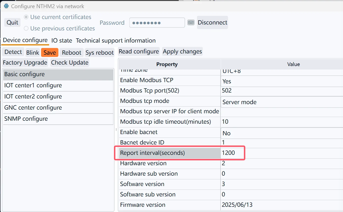
In particular, for SNMP Trap, it will not be reported regularly by default. You can enable the scheduled data reporting SNMP Trap in the SNMP settings.
Independently scheduled sending for AIO(Analogue Input Output)
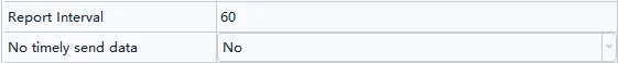
The sending interval can be set separately for each AIO. As shown in the figure below, in addition to reporting this temperature value when the device regularly reports all monitoring data (20 minutes by default), the temperature value will be reported separately at 60-second intervals.
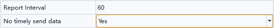
Disable scheduled sending
If the No timely send data is set, the temperature value will not be reported when the device periodically reports all monitoring data (20 minutes by default), and the separately set interval of 60 seconds will also be disabled. In this case, only the alarm is triggered or reported according to the following conditions.
Reported after monitoring the change of value
5.1) For AIO, if the Send Var Condition is set to non-0, the value will be reported as soon as the change reaches the threshold. As shown in the figure below, whenever the temperature value changes by more than 0.5, the latest value will be reported immediately, even if the timer time has not yet arrived.

5.2) For DIO, ENUM, and STRING types, it is sent whenever the value changes.
The alarm severity changes
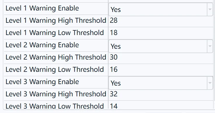
As shown in the figure below, when the temperature value changes to trigger an alarm (no alarm changes to a level 1 alarm), or the alarm level changes (a level 1 alarm changes to a level 2 alarm, or vice versa), the latest value will still be reported immediately even if the timer time has not expired and the value change has not been triggered.
IPv6
SNMP Trap support IPv6, Refer to the host configuration below:

Device MIB Description
The SNMP MIB of the Monigear equipment is mainly composed of productInfo and dioTable, aioTable, enumTable, and smTable.
The leaf node (OID) under productInfo is relatively fixed, which is used to read the product name, the total number of supervisory points of each type, and the number of modules.
The number of OIDs in the remaining five tables dynamically changes based on the device type. For example, there are two aioEntry under the aioTable for the Monigear-NTHM transmitter, which are temperature and humidity. The carbon dioxide transmitter has one aioEntry under the aioTable, which is CO2; Refer to the OID comparison table for commonly used devices.
The following is a detailed description of the device MIB OID(str represents OCTET STRING, int represents INTEGER32):
productInfo(.1.3.6.1.4.1.22853.1.1)
| Name | OID | Type | Description |
|---|---|---|---|
| productName | 1.0 | str | The product name of the device. |
| numSM | 2.0 | int | The total number of modules of the device (or supervisory unit), including the bus module and the virtual module, of which the device with address 0 is also counted as one, as shown in Figure 2. |
| numAIO | 3.0 | int | The total number of analog supervisory points (AIOs) of the device |
| numDIO | 4.0 | int | The total number of digital supervisory points (DIOs) of the device |
| numSTR | 5.0 | int | The total number of string supervisory points (DIOs) of the device |
| numENUM | 6.0 | int | The total number of enumeration supervisory points (DIOs) of the device |
dioTable(dioEntry, .1.3.6.1.4.1.22853.1.2.1)
| Name | OID | Type | Description |
|---|---|---|---|
| dioIndex | 1.Index | int | The index of all DIOs on the device (or supervisory unit). |
| dioValue | 2.Index | int | original value, 0 or 1 |
| dioAlarm | 3.Index | int | The current alarm level |
| dioSmaddr | 4.Index | int | The address of the module to which it belongs |
| dioRelindex | 5.Index | int | The relative index of the module to which it belongs |
| dioName | 6.Index | str | The name of the supervisory point |
| dioDetail | 7.Index | str | The displayed value string of the supervisory point is composed of the original value and the description corresponding to 0/1 |
Index indicates from 1 to numDIO.
aioTable(aioEntry, .1.3.6.1.4.1.22853.1.3.1)
| Name | OID | Type | Description |
|---|---|---|---|
| aioIndex | 1.Index | int | The index of all AIOs on the device (or supervisory unit). |
| aioValue | 2.Index | str | The original value, represented by floating-point numbers to strings |
| aioAlarm | 3.Index | int | The current alarm level |
| aioSmaddr | 4.Index | int | The address of the module to which it belongs |
| aioRelindex | 5.Index | int | The relative index of the module to which it belongs |
| aioName | 6.Index | str | The name of the supervisory point |
| aioDetail | 7.Index | str | The displayed value string of the supervisory point is a combination of the original value, accuracy, and unit |
Index indicates from 1 to numAIO.
strTable(strEntry, .1.3.6.1.4.1.22853.1.4.1)
| Name | OID | Type | Description |
|---|---|---|---|
| strIndex | 1.Index | int | The index of all STRs on the device (or supervisory unit). |
| strValue | 2.Index | str | String value |
| strAlarm | 3.Index | int | The current alarm level |
| strSmaddr | 4.Index | int | The address of the module to which it belongs |
| strRelindex | 5.Index | int | The relative index of the module to which it belongs |
| strName | 6.Index | str | The name of the supervisory point |
Index indicates from 1 to numSTR.
enumTable(enumEntry, .1.3.6.1.4.1.22853.1.5.1)
| Name | OID | Type | Description |
|---|---|---|---|
| enumIndex | 1.Index | int | The index of all ENUMs on the device (or supervisory unit). |
| enumValue | 2.Index | str | The original value of the integer type |
| enumAlarm | 3.Index | int | The current alarm level |
| enumSmaddr | 4.Index | int | The address of the module to which it belongs |
| enumRelindex | 5.Index | int | The relative index of the module to which it belongs |
| enumName | 6.Index | str | The name of the supervisory point |
| enumDetail | 7.Index | str | The displayed value string of the supervisory point is a combination of the original value and the enumeration string |
Index indicates from 1 to numENUM.
smTable(smEntry, .1.3.6.1.4.1.22853.1.6.1)
| Name | OID | Type | Description |
|---|---|---|---|
| smaddr | 1.Index | int | The index of all submodules of the device (or supervisory unit). |
| smDesc | 2.Index | str | The name of the module |
Index indicates from 1 to numSM.
SNMP OID table for some devices listed in Amazon
SNMP OID table of the original values of supervisory points of common Monigear devices.
Network temperature and humidity transmitters(MN-NHTM)
aioValue
| OID | Name | R/W | Unit | Remark |
|---|---|---|---|---|
| .1.3.6.1.4.1.22853.1.3.1.2.1 | Temperature | R | ℃/℉ | -30-85 ℃ |
| .1.3.6.1.4.1.22853.1.3.1.2.2 | Humidity | R | %RH | 0-100 %RH |
Network CO2 transmitters(MN-NCO2)
aioValue
| OID | Name | R/W | Unit | Remark |
|---|---|---|---|---|
| .1.3.6.1.4.1.22853.1.3.1.2.1 | CO2 | R | ppm | 400-2000 ppm |
Carbon dioxide+temperature and humidity 3in1(MN-NCO2TH)
aioValue
| OID | Name | R/W | Unit | Remark |
|---|---|---|---|---|
| .1.3.6.1.4.1.22853.1.3.1.2.1 | CO2 | R | ppm | 400-2000 ppm |
| .1.3.6.1.4.1.22853.1.3.1.2.2 | Temperature | R | ℃/℉ | -30-85 ℃ |
| .1.3.6.1.4.1.22853.1.3.1.2.3 | Humidity | R | % RH | 0-100 %RH |
TVOC/Co2/Temperature/Humidity 4in1 (MN-NVOC)
aioValue
| OID | Name | R/W | Unit | Remark |
|---|---|---|---|---|
| .1.3.6.1.4.1.22853.1.3.1.2.1 | CO2 | R | ppm | 400-2000 ppm |
| .1.3.6.1.4.1.22853.1.3.1.2.2 | Temperature | R | ℃/℉ | -30-85 ℃ |
| .1.3.6.1.4.1.22853.1.3.1.2.3 | Humidity | R | % RH | 0-100 %RH |
| .1.3.6.1.4.1.22853.1.3.1.2.3 | TVOC | R | ppb | 0-65000ppb |
General IO monitor(MN-NIO)
dioValue
| OID | Name | R/W | Description | Remark |
|---|---|---|---|---|
| .1.3.6.1.4.1.22853.1.2.1.2.1 | DI1 | R | 0: Close 1: Open | Digital input 1 |
| .1.3.6.1.4.1.22853.1.2.1.2.2 | DI2 | R | 0: Close 1: Open | Digital input 2 |
| .1.3.6.1.4.1.22853.1.2.1.2.3 | DI3 | R | 0: Close 1: Open | Digital input 3 |
| .1.3.6.1.4.1.22853.1.2.1.2.4 | DI4 | R | 0: Close 1: Open | Digital input 4 |
| .1.3.6.1.4.1.22853.1.2.1.2.5 | DI5 | R | 0: Close 1: Open | Digital input 5 |
| .1.3.6.1.4.1.22853.1.2.1.2.6 | DI6 | R | 0: Close 1: Open | Digital input 6 |
| .1.3.6.1.4.1.22853.1.2.1.2.7 | DI7 | R | 0: Close 1: Open | Digital input 7 |
| .1.3.6.1.4.1.22853.1.2.1.2.8 | DI8 | R | 0: Close 1: Open | Digital input 8 |
| .1.3.6.1.4.1.22853.1.2.1.2.9 | DO9 | RW | 0: Close 1: Open | Digital output 1 |
| .1.3.6.1.4.1.22853.1.2.1.2.10 | DO10 | RW | 0: Close 1: Open | Digital output2 |
| .1.3.6.1.4.1.22853.1.2.1.2.11 | DO11 | RW | 0: Close 1: Open | Digital output3 |
| .1.3.6.1.4.1.22853.1.2.1.2.12 | DO12 | RW | 0: Close 1: Open | Digital output 4 |
Note: The general digital input interface corresponds to the dry junction sensor, and the actual name and 0/1 value description of each channel are defined depending on the sensor type. For example, the smoke alarm connected to DI1 is actually called smoke detector status, 0: normal 1: alarm.
aioValue
| OID | Name | R/W | Unit | Remark |
|---|---|---|---|---|
| .1.3.6.1.4.1.22853.1.3.1.2.1 | AI1 | R | \ | Analog input 1 |
| .1.3.6.1.4.1.22853.1.3.1.2.2 | AI2 | R | \ | Analog input 2 |
| .1.3.6.1.4.1.22853.1.3.1.2.3 | AI3 | R | \ | Analog input 3 |
| .1.3.6.1.4.1.22853.1.3.1.2.4 | AI4 | R | \ | Analog input 4 |
| .1.3.6.1.4.1.22853.1.3.1.2.5 | AI5 | R | \ | Analog input 5 |
| .1.3.6.1.4.1.22853.1.3.1.2.6 | AI6 | R | \ | Analog input 6 |
| .1.3.6.1.4.1.22853.1.3.1.2.7 | AI7 | R | \ | Analog input 7 |
| .1.3.6.1.4.1.22853.1.3.1.2.8 | AI8 | R | \ | Analog input 8 |
Note: The general analogue input interface connect a industrial standard 4-20mA sensors, and the actual name and unit of each channel depends on the sensor type. For example, AI1 is connected to a 4-20mA water level transmitter, which is actually called water level and unit is in meters. In addition, the upper and lower limits of analog quantities are further set according to the range of the sensor.
Other main host or gateway type devices of our company have many more OIDs, but the organizational form is similar to the above products.
Appendix A- Data Types of acquisition
The Monigear device represents the status data collected by the front-end sensor in the form of a supervisory point (SP), which is divided into four basic types: digital input/output(DIO), analog input/output(AIO), enumeration ENUM and string STRING.
| SP Type | DigitalDIO | AnalogueAIO | enumeration ENUM | STRING |
|---|---|---|---|---|
| Data type | Bool(0/1) | Float | Int | String |
| Example | Smoke sensorMotion detector | Temperaturevoltage | UPS、Generator status | IC card number |
Monigear devices have certain storage and computing capabilities, and can process the collected raw data on the device side and then report it to the server side, such as converting from raw values to displayed values, triggering alarms based on preset thresholds, executing linkage actions, etc. The following further explains the collected data values and alarm related contents.
Original value and displayed value
The raw value of the Monigear device data represents the data directly obtained from the sensor. When users read the device data through the standard communication protocol, they usually only care about the raw value. In some cases, the raw value is not easy to understand (for example, the two example DIOs in the following text have raw values of 1, one for water leak alarm and the other for normal), and it is necessary to combine the sensor information to get a readable display value corresponding to the monitored entity for the user.
Monigear devices provide corresponding conversion configurations for different types of monitoring points for users to modify (or refer to). Some communication protocols (such as SNMP GET) can directly read the conversion results. The following is an example of the conversion of original values and displayed values of each type. For a detailed description of monitoring point attributes, refer to the appendix B.
① dioValue和dioDetail
| dioValue | D0 descr | D1 descr | dioDetail |
|---|---|---|---|
| 1 | Normal | Leak alarm | Water leak |
| dioValue | D0 descr | D1 descr | dioDetail |
|---|---|---|---|
| 1 | Smoke alarm | Normal | Normal |
② aioValue和aioDetail
| Original | Precision | Unit | Display |
|---|---|---|---|
| 237.5146 | 0.0 | V | 237.5V |
③ enumValue和enumDetail
| Original | Enum string | Display |
|---|---|---|
| 1 | 0, No output1,Main power supply2,Battery supply…… | Main power supply |
④ strValue
Strings do not need to distinguish between raw and displayed values.
SP Alarm
Each supervisory point of the Monigear device can set an alarm individually, support delayed alarm, and provide up to 3 levels of alarms, usually level 3 is an emergency alarm, level 2 is an important alarm, and level 1 is a normal alarm. For the settings of various types of alarms, refer to the appendix B.
After the alarm is triggered, some communication protocols (such as SNMP GET, MQTT) can directly read the current alarm level. In addition, you can choose to send an email after the alarm, execute linkage actions (such as MN-NIO, control relay actions), etc.
Appendix B-Supervisory Point Configuration
DIO(Digital Input Output) Digital input and output configuration: including whether the channel is enabled, the value for alarm, the alarm level, whether it is a security monitoring point, delayed alarm time, etc.
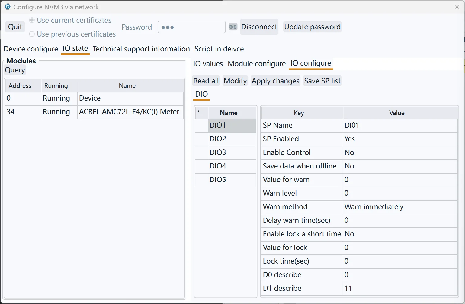
| DIO Property | Value | Description |
|---|---|---|
| SP Name | The description of the DIO SP | |
| SP Enabled | Yes | This SP is enabled and the data will be reported to the center when conditions are met. |
| No | This SP is not enabled and will not be reported to the center. | |
| Enable Control | Yes | Digital output like relay that can be control |
| No | Digital input that cannot be controlled should be No | |
| Save data when offline | Yes | Keep the history data |
| No | Don’t keep the history data | |
| Value for warn | 0 | Digital value 0 is value for alarm |
| 1 | Digital value 1 is value for alarm | |
| Warn level | This item can only be 0, 1, 2, or 3 (0 means the alarm is not enabled) | |
| Warn method | Warn immediately | When the digital value is the same as the alarm value, an alarm is generated immediately. |
| Warn after delay a period | The digital value is the same as the alarm value and keep for a period of time then the alarm is generated. | |
| Delay warn time | Use with the previous item | |
| Enable lock a short time | Used for security SPs. Frequently changing digital signals will cause frequent alarms. Enabling this function can solve the problem of frequent alarms. | |
| Value for lock | When a state is locked for a period of time, if the digital input value changes to the locked value, the SP value will remain locked during the locked time, regardless of whether the value of the actual SP value changes during this period. | |
| Lock time | When the lock function is enabled, the SP remains unchanged for a certain period of time. |
AIO(Analog Input Output) Analog input and output configuration: including whether the channel is enabled, precision, unit, upper and lower limits of effective value, alarm level, delayed alarm time, etc.
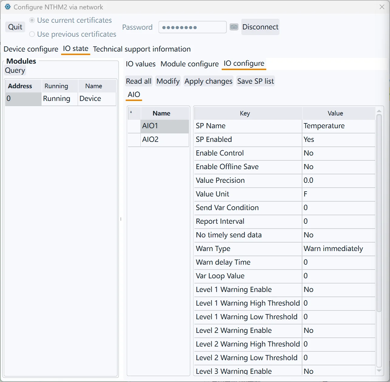
| AIO Properies | Value | Description |
|---|---|---|
| SP Name | Functional description of analog monitoring points | |
| SP Enabled | Yes | This SP is enabled and the data will be reported to the center when conditions are met. |
| No | This SP is not enabled and will not be reported to the center. | |
| Enable Control | Yes | For an analogue output |
| No | For an analogue input | |
| Enable Offline save | Yes | Save the history data |
| No | Don’t save history data | |
| Value Precision | The display precision of the SP value, for example, if it is set to 0.0, one decimal place will be retained | |
| Value Unit | The unit of the monitoring value, such as meter, ℃, etc. | |
| Send Var Condition | If the deviation between the monitored value and the last reported value is greater than this value, the monitored data will be immediately reported to the data center. | |
| Report interval | The frequency at which the SP is reported to the data center. If it is 0, the default system reporting interval is used (in the basic configuration category, the default is 20 minutes) | |
| No timely send data | Yes | When the device reports all monitoring data regularly, the value of this monitoring point is not reported. |
| No | When the device reports all SP data regularly, it reports the value of the monitoring point | |
| Warn Type | Warn immediately | When the monitoring value is higher than the upper alarm limit or lower than the lower alarm limit, an alarm is immediately issued |
| Warn after delay a period | An alarm is generated only when the monitoring value is higher than the upper alarm limit or lower than the lower alarm limit and keep for a period of time. | |
| Warn delay time | Use with the previous item | |
| Var loop value | The difference between the monitoring value and the alarm threshold must be greater than the loopback protection threshold value to meet the alarm cancellation condition, which can avoid frequent alarm triggering near the critical point. For example, if the alarm is set to be greater than 36°, if this value is set to 0.5, the alarm state will be cancelled only when the value is less than 35.5. | |
| Level 1/2/3 Warning Eanble | When the monitoring value meets the conditions, an alarm of the corresponding level will be generated | |
| Level 1/2/3 warning high threshold | When the monitoring value is higher than the alarm upper threshold, an alarm of the corresponding level will be generated | |
| Level 1/2/3 waring low threshold | When the monitoring value is lower than the alarm lower threshold, an alarm of the corresponding level will be generated | |
| Minimum value | The lower limit of the external transmitter range | |
| Maximum value | The upper limit of the external transmitter range |